Requirements for Alert Logic Managed Web Application Firewall (WAF) for Amazon Web Services
 United States firewall rules for marketplace customers
Use the following rules to communicate with the US Data Center.
Inbound appliance
| Port | Protocol | CIDR | Description |
|---|---|---|---|
| 22 | TCP | 204.110.219.96/27 | Management SSH access from Alert Logic Data center |
| 22 | TCP | 204.110.218.96/27 | Management SSH access from Alert Logic - Backup Data center |
| 4849 | TCP | 204.110.219.96/27 | Management GUI access from Alert Logic Central UI Data center |
| 4849 | TCP | 204.110.218.96/27 | Management GUI access fromAlert Logic Central UI - Backup Data center |
| 80 | TCP | 0.0.0.0/0 | HTTP traffic from the Internet |
| 443 | TCP | 0.0.0.0/0 | HTTPS traffic from the Internet |
| 4849 | TCP | User Source IP CIDR | Management GUI access from User provided CIDR |

The Security Group that is bundled with the appliance in Amazon Web Services Marketplace contains the inbound rules except for the one highlighted, which is required for the management and license activation page to be accessible from your IP. You need to add that to the Security Group when the Amazon Machine Image (AMI) is launched.
Outbound appliance
| Port | Protocol | CIDR | Description |
|---|---|---|---|
| 443 | TCP | 204.110.219.96/27 | Data transport and updates - Alert Logic Data center |
| 443 | TCP | 204.110.218.96/27 | Data transport and updates - Alert Logic Backup Data center |
The Security Group outbound rules default to 0.0.0.0/0 for all ports but can be restricted to the outbound rules above, if required.
 European Union firewall rules for marketplace customers
Use the following rules to communicate with the EU Data Center.
Inbound appliance
| Port | Protocol | CIDR | Description |
|---|---|---|---|
| 22 | TCP | 204.110.219.96/24 | Management SSH access from Alert Logic Data center |
| 22 | TCP | 204.110.218.96/24 | Management SSH access from Alert Logic - Backup Data center |
| 4849 | TCP | 204.110.219.96/24 | Management GUI access from Alert Logic Central UI Data center |
| 4849 | TCP | 204.110.218.96/24 | Management GUI access fromAlert Logic Central UI - Backup Data center |
| 80 | TCP | 0.0.0.0/0 | HTTP traffic from the Internet |
| 443 | TCP | 0.0.0.0/0 | HTTPS traffic from the Internet |
| 4849 | TCP | User Source IP CIDR | Management GUI access from User provided CIDR |
The Security Group that is bundled with the appliance in Amazon Web Services Marketplace contains the inbound rules except for the one highlighted, which is required for the management and license activation page to be accessible from your IP. You need to add that to the Security Group when the Amazon Machine Image (AMI) is launched.
Outbound appliance
| Port | Protocol | CIDR | Description |
|---|---|---|---|
| 443 | TCP | 204.110.219.96/27 | Data transport and updates - Alert Logic Data center |
| 443 | TCP | 204.110.218.96/27 | Data transport and updates - Alert Logic Backup Data center |
The Security Group outbound rules default to 0.0.0.0/0 for all ports but can be restricted to the outbound rules above, if required.
United States firewall rules for direct customers
Use the following rules to communicate with the US Data Center.
Master ELB - inbound rules
|
Inbound |
Port |
Source |
Destination |
Description |
|---|---|---|---|---|
|
Inbound to Master ELB from Alert Logic |
4849 |
Alert Logic |
Master ELB |
The Master ELB accepts incoming connections on TCP port 4849 from the Alert Logic address space (204.110.218.96/27 and 204.110.219.96/27) for management of the Master via the Master ELB.
Management operations include:
|
|
Inbound to Master ELB from Alert Logic |
2222 |
Alert Logic |
Master ELB |
The Master ELB and Worker ELB accept incoming connections on TCP port 2222 from the Alert Logic address space (204.110.218.96/27 and 204.110.219.96/27) for the Alert Logic Security Operations monitoring. |
|
Inbound to Master ELB from Customer Office |
4849 |
Customer Office |
Master ELB |
The Master ELB accepts incoming connections on TCP port 4849 from their customer CIDR for emergency management of the Master instance via the Master ELB. |
Master ELB - outbound rules
|
Outbound |
Port |
Source |
Destination |
Description |
|---|---|---|---|---|
|
Outbound from Master ELB to Master |
4849 |
Master ELB |
Master |
The Master ELB makes outbound connections to the Master on port 4849 for access to the GUI |
|
Outbound from Master ELB to Master |
22 |
Master ELB |
Master |
The Master ELB makes outbound connections to the Master on port 22 for the SOC monitoring. |
|
Outbound from Master ELB to Master |
4848 |
Master ELB |
Master |
The Master ELB makes outbound connections to the Master on port 4848 for health management of the Master. |
Master - inbound rules
|
Inbound |
Port |
Source |
Destination |
Description |
|---|---|---|---|---|
|
Inbound to Master from Master ELB |
4849 |
Master ELB |
Master |
The Master accepts incoming connections on port 4849 for access to the GUI. |
|
Inbound to Master from Master ELB |
22 |
Master ELB |
Master |
The Master accepts incoming connections on port 22 for the Alert Logic Security Operations monitoring. |
|
Inbound to Master from Master ELB |
4848 |
Master ELB |
Master |
The Master accepts incoming connections on port 4848 from the Master ELB for health management of the Master. |
|
Inbound to Master from Worker |
2625 |
Worker |
Master |
The Master accepts incoming connections on TCP 2625 from the Worker for the transfer of statistics between the Worker and Master. |
|
Inbound to Master from Worker |
5556 |
Worker |
Master |
The Master accepts incoming connections on TCP 5556 from the Worker for the transfer of Deny log data from the Worker to the Master. |
| Inbound to Master from Worker | 5559 | Worker | Master | The Master accepts incoming connections on TCP 5559 from the Worker for communication HUB between Master and Worker. |
| Inbound to Master from Worker | 5560 | Worker | Master | The Master accepts incoming connections on TCP 5560 from the Worker for communication HUB between Master and Worker. |
|
Inbound to Master from Worker |
123 |
Worker |
Master |
The Master accepts incoming connections on UDP 123 from the Worker for NTP time synchronization requests. |
|
Inbound to Master from Worker |
514 |
Worker |
Master |
The Master accepts incoming connections on UDP 514 from the Worker for log data transfer from Worker to Master. |
Master - outbound rules
|
Outbound |
Port |
Source |
Destination |
Description |
|---|---|---|---|---|
|
Outbound from Master to Alert Logic |
443 |
Master |
Alert Logic |
The Master makes outbound connections on TCP 443 to the Alert Logic address space (204.110.218.96/27 and 204.110.219.96/27) for access to Alert Logic.
Management operations include:
|
|
Outbound from Master to any IP address |
443 |
Master |
Any IP address |
The Master makes outbound connections on TCP port 443 to the internet (0.0.0.0/0) for HTTPS traffic to Amazon S3 via any IP address. |
|
Outbound from Master to Worker |
22 |
Master |
Worker |
The Master makes outbound connections on TCP 22 to the Worker for management of the Worker. |
| Outbound from Master to Worker | 5559 | Master | Worker | The Master makes outbound connections on TCP 5559 to workers for communication HUB between Master and Worker. |
| Outbound from Master to Worker | 5560 | Master | Worker | 5560 to workers for communication HUB between Master and Worker. |
|
Outbound from Master to Web server |
80 |
Master |
Web server |
The Master makes outbound connections to the Web server on port TCP 80 to verify connectivity. |
Worker ELB - inbound rules
|
Inbound |
Port |
Source |
Destination |
Description |
|---|---|---|---|---|
|
Inbound to Worker ELB from Internet |
80 |
Internet |
Worker ELB |
The Worker accepts incoming connections on TCP port 80 from the internet (0.0.0.0/0) for the acceptance of HTTP web traffic. |
|
Inbound to Worker ELB from Internet |
443 |
Internet |
Worker ELB |
The Worker accepts incoming connections on TCP port 443 from the internet (0.0.0.0/0) for the acceptance of HTTPS web traffic. |
Worker ELB - outbound rules
|
Outbound |
Port |
Source |
Destination |
Description |
|---|---|---|---|---|
|
Outbound from Worker ELB to Worker |
80 |
Worker ELB |
Worker |
The Worker ELB makes outbound connections to the Worker on port TCP 80 to process HTTP traffic. |
|
Outbound from Worker ELB to Worker |
4848 |
Worker ELB |
Worker |
The Worker makes outbound connections to the Worker on port 4848 for health management of the Worker. |
Worker - inbound rules
|
Inbound |
Port |
Source |
Destination |
Description |
|---|---|---|---|---|
|
Inbound to Worker from Master |
22 |
Master |
Worker |
The Worker accepts incoming connections on TCP port 22 from the Master for management of the Worker. |
| Inbound to Worker from Master | 5559 | Master | Worker | The Worker accepts incoming connections on TCP port 5559 from the Master for communication HUB between master and workers. |
| Inbound to Master from Worker | 5560 | Master | Worker | The Worker accepts incoming connections on TCP 5560 from the Master for communication HUB between master and workers. |
|
Inbound to Worker from Worker ELB |
80 |
Worker ELB |
Worker |
The Worker accepts incoming connections on TCP port 80 from Worker ELB for the acceptance of HTTP web traffic. |
|
Inbound to Worker from Worker ELB |
443 |
Worker ELB |
Worker |
The Worker accepts incoming connections on TCP port 443 from Worker ELB for the acceptance of HTTPS web traffic. |
|
Inbound to Worker from Worker ELB |
4848 |
Worker ELB |
Worker |
The Worker accepts incoming connections on TCP port 4848 from the Worker ELB for health management of the Worker ELB. |
Worker - outbound rules
|
Outbound |
Port |
Source |
Destination |
Description |
|---|---|---|---|---|
|
Outbound from Worker to Master |
5556 |
Worker |
Master |
The Worker makes outbound connections on TCP 5556 to the Master for the transfer of Deny log data from the Worker to the Master. |
| Outbound from Worker to Master | 5559 | Worker | Master | The Worker makes outbound connections on TCP 5559 to the Master for communication HUB between Worker and Master. |
| Outbound from Worker to Master | 5560 | Worker | Master | The Worker makes outbound connections on TCP 5560 to the Master for communication HUB between Worker and Master. |
|
Outbound from Worker to Master |
2625 |
Worker |
Master |
The Worker makes outbound connections on TCP 2625 to the Master for the transfer of statistics between the Worker and Master. |
|
Outbound from Worker to Master |
123 |
Worker |
Master |
The Worker makes outbound connections on UDP 123 to the Master for NTP time synchronization requests. |
|
Outbound from Worker to Master |
514 |
Worker |
Master |
The Worker makes outbound connections on UDP 514 to the Master for Log data transfer from Worker to Master. |
|
Outbound from Worker to Amazon S3 bucket and Alert Logic backend |
443 |
Worker |
Amazon S3 and Alert Logic backend |
The Worker makes outbound connections on TCP 443 to the internet (0.0.0.0/0) for access to S3 and the Alert Logic backend. |
European Union firewall rules for direct customers
Use the following rules to communicate with the EU Data Center.
Master ELB - inbound rules
|
Inbound |
Port |
Source |
Destination |
Description |
|---|---|---|---|---|
|
Inbound to Master ELB from Alert Logic |
4849 |
Alert Logic |
Master ELB |
The Master ELB accepts incoming connections on TCP port 4849 from the Alert Logic address space (204.110.218.96/24 and 204.110.219.96/24) for management of the Master via the Master ELB.
Management operations include:
|
|
Inbound to Master ELB from Alert Logic |
2222 |
Alert Logic |
Master ELB |
The Master ELB and Worker ELB accept incoming connections on TCP port 2222 from the Alert Logic address space (185.54.124.0/24) for the Alert Logic Security Operations monitoring. |
|
Inbound to Master ELB from Customer Office |
4849 |
Customer Office |
Master ELB |
The Master ELB accepts incoming connections on TCP port 4849 from their customer CIDR for emergency management of the Master instance via the Master ELB. |
Master ELB - outbound rules
|
Outbound |
Port |
Source |
Destination |
Description |
|---|---|---|---|---|
|
Outbound from Master ELB to Master |
4849 |
Master ELB |
Master |
The Master ELB makes outbound connections to the Master on port 4849 for access to the GUI |
|
Outbound from Master ELB to Master |
22 |
Master ELB |
Master |
The Master ELB makes outbound connections to the Master on port 22 for the Alert Logic Security Operations monitoring. |
|
Outbound from Master ELB to Master |
4848 |
Master ELB |
Master |
The Master ELB makes outbound connections to the Master on port 4848 for health management of the Master. |
Master - inbound rules
|
Inbound |
Port |
Source |
Destination |
Description |
|---|---|---|---|---|
|
Inbound to Master from Master ELB |
4849 |
Master ELB |
Master |
The Master accepts incoming connections on port 4849 for access to the GUI. |
|
Inbound to Master from Master ELB |
22 |
Master ELB |
Master |
The Master accepts incoming connections on port 22 for the Alert Logic Security Operations monitoring. |
|
Inbound to Master from Master ELB |
4848 |
Master ELB |
Master |
The Master accepts incoming connections on port 4848 from the Master ELB for health management of the Master. |
|
Inbound to Master from Worker |
2625 |
Worker |
Master |
The Master accepts incoming connections on TCP 2625 from the Worker for the transfer of statistics between the Worker and Master. |
|
Inbound to Master from Worker |
5556 |
Worker |
Master |
The Master accepts incoming connections on TCP 5556 from the Worker for the transfer of Deny log data from the Worker to the Master. |
| Inbound to Master from Worker | 5559 | Worker | Master | The Master accepts incoming connections on TCP 5559 from the Worker for communication HUB between Master and Worker. |
| Inbound to Master from Worker | 5560 | Worker | Master | The Master accepts incoming connections on TCP 5560 from the Worker for communication HUB between Master and Worker. |
|
Inbound to Master from Worker |
123 |
Worker |
Master |
The Master accepts incoming connections on UDP 123 from the Worker for NTP time synchronization requests. |
|
Inbound to Master from Worker |
514 |
Worker |
Master |
The Master accepts incoming connections on UDP 514 from the Worker for log data transfer from Worker to Master. |
Master - outbound rules
|
Outbound |
Port |
Source |
Destination |
Description |
|---|---|---|---|---|
|
Outbound from Master to Alert Logic |
443 |
Master |
Alert Logic |
The Master makes outbound connections on TCP 443 to the Alert Logic address space (204.110.218.96/24 and 204.110.219.96/24) for access to Alert Logic.
Management operations include:
|
|
Outbound from Master to any IP address |
443 |
Master |
Any IP address |
The Master makes outbound connections on TCP port 443 to the internet (0.0.0.0/0) for HTTPS traffic to Amazon S3 via any IP address. |
|
Outbound from Master to Worker |
22 |
Master |
Worker |
The Master makes outbound connections on TCP 22 to the Worker for management of the Worker. |
| Outbound from Master to Worker | 5559 | Master | Worker | The Master makes outbound connections on TCP 5559 for communication HUB between Master and Worker. |
| Outbound from Master to Worker | 5560 | Master | Worker | The Master makes outbound connections on TCP 5560 for communication HUB between Master and Worker. |
|
Outbound from Master to Web server |
80 |
Master |
Web server |
The Master makes outbound connections to the Web server on port TCP 80 to verify connectivity. |
Worker ELB - inbound rules
|
Inbound |
Port |
Source |
Destination |
Description |
|---|---|---|---|---|
|
Inbound to Worker ELB from Internet |
80 |
Internet |
Worker ELB |
The Worker accepts incoming connections on TCP port 80 from the internet (0.0.0.0/0) for the acceptance of HTTP web traffic. |
|
Inbound to Worker ELB from Internet |
443 |
Internet |
Worker ELB |
The Worker accepts incoming connections on TCP port 443 from the internet (0.0.0.0/0) for the acceptance of HTTPS web traffic. |
Worker ELB - outbound rules
|
Outbound |
Port |
Source |
Destination |
Description |
|---|---|---|---|---|
|
Outbound from Worker ELB to Worker |
80 |
Worker ELB |
Worker |
The Worker ELB makes outbound connections to the Worker on port TCP 80 to process HTTP traffic. |
|
Outbound from Worker ELB to Worker |
4848 |
Worker ELB |
Worker |
The Worker makes outbound connections to the Worker on port 4848 for health management of the Worker. |
Worker - inbound rules
|
Inbound |
Port |
Source |
Destination |
Description |
|---|---|---|---|---|
|
Inbound to Worker from Master |
22 |
Master |
Worker |
The Worker accepts incoming connections on TCP port 22 from the Master for management of the Worker. |
| Inbound to Worker from Master | 5559 | Master | Worker | The Worker accepts incoming connections on TCP port 5559 from the Master for communication HUB between master and workers. |
| Inbound to Master from Worker | 5560 | Master | Worker | The Worker accepts incoming connections on TCP 5560 from the Master for communication HUB between master and workers. |
|
Inbound to Worker from Worker ELB |
80 |
Worker ELB |
Worker |
The Worker accepts incoming connections on TCP port 80 from Worker ELB for the acceptance of HTTP web traffic. |
|
Inbound to Worker from Worker ELB |
443 |
Worker ELB |
Worker |
The Worker accepts incoming connections on TCP port 443 from Worker ELB for the acceptance of HTTPS web traffic. |
|
Inbound to Worker from Worker ELB |
4848 |
Worker ELB |
Worker |
The Worker accepts incoming connections on TCP port 4848 from the Worker ELB for health management of the Worker ELB. |
Worker - outbound rules
|
Outbound |
Port |
Source |
Destination |
Description |
|---|---|---|---|---|
|
Outbound from Worker to Master |
5556 |
Worker |
Master |
The Worker makes outbound connections on TCP 5556 to the Master for the transfer of Deny log data from the Worker to the Master. |
| Outbound from Worker to Master | 5559 | Worker | Master | The Worker makes outbound connections on TCP 5559 to the Master for communication HUB between Worker and Master. |
| Outbound from Worker to Master | 5560 | Worker | Master | The Worker makes outbound connections on TCP 5560 to the Master for communication HUB between Worker and Master. |
|
Outbound from Worker to Master |
2625 |
Worker |
Master |
The Worker makes outbound connections on TCP 2625 to the Master for the transfer of statistics between the Worker and Master. |
|
Outbound from Worker to Master |
123 |
Worker |
Master |
The Worker makes outbound connections on UDP 123 to the Master for NTP time synchronization requests. |
|
Outbound from Worker to Master |
514 |
Worker |
Master |
The Worker makes outbound connections on UDP 514 to the Master for Log data transfer from Worker to Master. |
|
Outbound from Worker to Amazon S3 bucket and Alert Logic backend |
443 |
Worker |
Amazon S3 and Alert Logic backend |
The Worker makes outbound connections on TCP 443 to the internet (0.0.0.0/0) for access to S3 and the Alert Logic backend. |
Availability zones and AWS instance types
Before you deploy the Managed WAF stack for one your production web applications, you should consider the availability zones and AWS instance types that would work best in your environment.
Availability zones
Managed WAF supports any number of availability zones within a single AWS Region. The CloudFormation template configures an even distribution of worker nodes across availability zones and maintains, at minimum, a number of worker nodes equal to the number of availability zones. For example two availability zones must always have at least two Managed WAF workers.
If you need to modify the CloudFormation template to support more than the default two availability zones, contact Alert Logic by e-mail at support@alertlogic.com or by phone at (877) 484-8383. In the EU, call (877) 484-8383.
AWS instance type
Managed WAF workers and master appliances are bound to specific AWS instance types. Master appliances run on General Purpose Medium and Large instance types. Worker appliances run on General Purpose Small and Compute Optimized Medium and Xlarge instance types. The default instance types are c4.large for workers and m3.large for the master. This configuration processes approximately 100 Mbps of inbound and outbound web traffic in a two-worker deployment before autoscaling. The CloudFormation template allows for selecting instance types when run.
Master instance processing capacity
The m3.large instance suffices for most installations. An EBS volume outside the master persists the log and configuration data, and you can easily upgrade the master appliance by using the CloudFormation template to specify a new master instance type.
Master instance processing capacity is approximately:
| Instance Type | Workers Capacity | Traffic Capacity | EBS Volume Size |
|---|---|---|---|
| m3medium | 10 Workers | 100 Mbps | 100 GB, SSD |
| m3.large | 10 Workers | 250 Mbps | 100 GB, SSD |
| m3.xlarge | 25 Workers | 1000 Mbps | 300 GB, SSD |
Master instances are not processing traffic inline. Traffic capacity is the master's ability to process data from the Learner and deny logs at near real-time as workers deliver the data. Average performance is measured using a representative sample of e-commerce web traffic. Actual performance may vary and depends on factors such as ratio of inbound to outbound traffic, request complexity, variability in input, and concurrency.
The EBS volume size is the minimum recommended. The EBS volume is used to store log data in transit to the Alert Logic backend and Deny Log data used for tuning. If the EBS volume disk space runs out, the Web Security Manager instance will stop logging and issue an alert to the Alert Logic monitoring system. This condition will not affect availability of the Web Security Manager autoscaling stack.
Worker instance processing capacity
Because Web Security Manager scales up or down to accommodate changes in traffic load, the size and initial number of worker instances can be optimized to serve expected daily traffic rather than optimizing for peak traffic load as is required where processing capacity is static.
Worker instance processing capacity:
| Instance Type | Traffic Capacity | EBS Volume Size | EBS Volume with Caching |
|---|---|---|---|
| c3.large | 70 Mbps | 8 GB, SSD | 100 GB, SSD |
| c3.xlarge | 140 Mbps | 8 GB, SSD | 100 GB, SSD |
| c3.2xlarge | 280 Mbps | 8 GB, SSD | 100 GB, SSD |
| c3.4xlarge | 550 Mbps | 8 GB, SSD | 100 GB, SSD |
| c4.large | 80 Mbps | 8 GB, SSD | 100 GB, SSD |
| c4.xlarge | 160 Mbps | 8 GB, SSD | 100 GB, SSD |
| c4.2xlarge | 310 Mbps | 8 GB, SSD | 100 GB, SSD |
| c4.4xlarge | 620 Mbps | 8 GB, SSD | 100 GB, SSD |
Traffic capacity is an average performance measured using a representative sample of e-commerce web traffic. Actual performance may vary and depends on factors such as ratio of inbound to outbound traffic, request complexity, variability in input, and concurrency.
The EBS volume size is the minimum recommended. The EBS volume is used for caching and as a temporary store for log data in transit to the master instance. If traffic caching is not enabled it is possible to run with smaller volume sizes. Cache directory sizing is configured dynamically relative to the available disk space so with smaller volume sizes the cache will be smaller. If the EBS volume disk space runs out, the Web Security Manager instance will stop logging and issue an alert to the Alert Logic monitoring system.
Autoscaling stack performance
Workers are deployed in pools, so the actual capacity depends on the number of workers in the load balancing pool. The table below shows the average traffic processing capacity, in Mbps, for the different Amazon instance types when traffic is distributed evenly across all workers in all availability zones.
| One availability zone | Two availability zones | Three availability zones | |||||||
|---|---|---|---|---|---|---|---|---|---|
| Autoscaling step | 1 | 2 | 3 | 1 | 2 | 3 | 1 | 2 | 3 |
| Number of workers | 1 | 2 | 3 | 2 | 4 | 6 | 3 | 6 | 9 |
| c3.large | 70 | 140 | 210 | 140 | 280 | 420 | 210 | 420 | 630 |
| c3.xlarge | 140 | 280 | 420 | 280 | 560 | 840 | 420 | 840 | 1260 |
| c3.2xlarge | 280 | 560 | 840 | 560 | 1120 | 1680 | 840 | 1680 | 2520 |
| c3.4xlarge | 550 | 1100 | 1650 | 1100 | 2200 | 3300 | 1650 | 3300 | 4950 |
| c4.large | 80 | 160 | 240 | 160 | 320 | 480 | 240 | 480 | 720 |
| c4.xlarge | 160 | 320 | 480 | 320 | 620 | 960 | 480 | 960 | 1440 |
| c4.2xlarge | 310 | 620 | 930 | 620 | 1240 | 1860 | 930 | 1860 | 2790 |
| c4.4xlarge | 620 | 1240 | 1860 | 1240 | 2480 | 3720 | 1860 | 3720 | 5580 |
Autoscaling parameters
The CloudFormation template allows you to define autoscaling parameters. The default configuration adds workers to the load balancing pool when the average CPU utilization is high for a few minutes, and does not scale down until CPU utilization is below the threshold at which the remaining workers can process the workload without immediately scaling up again for a much longer period.
The difference in thresholds for scaling up and scaling down serves to mitigate the rist of removing capacity too quickly, or incorrectly reducing capacity. For more information, see Amazon Autoscaling documentation.
Environment requirements
Before you deploy Managed WAF for Amazon Web Services, be sure your environment conforms to the standards described in this section. For deployments and environments that vary from the recommended configuration, please contact Alert Logic by e-mail at support@alertlogic.com or by phone at (877) 484-8383. In the EU, call (877) 484-8383.
Deployment environment
The CloudFormation template, which creates all Managed WAF specific resources, deploys the Autoscaling Managed WAF stack as outlined below.
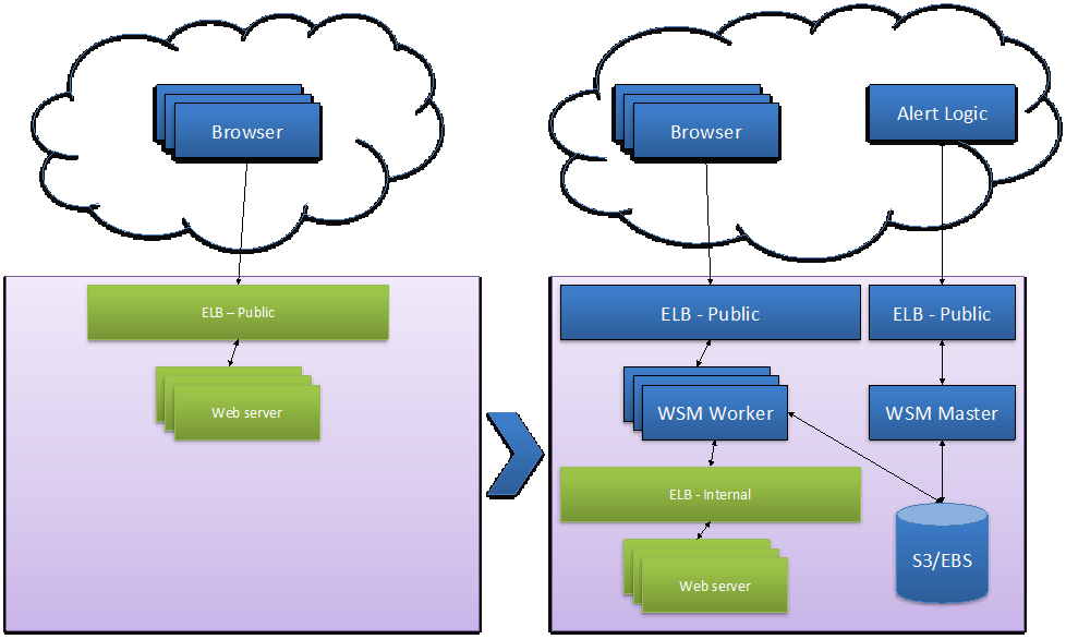
When deploying in front of an existing load balanced Web pool, the CloudFormation template creates an extra load balanced layer of WAFs in front of the Web server pool.
The CloudFormation template deploys the Managed WAF Worker load balancing pool as an autoscaling group to adapt to variations in workload. The Managed WAF Workers are deployed behind an Internet-facing elastic load balancer (ELB) and reach your backend Web servers through an internal ELB that load balances traffic to the Web servers.
The Managed WAF master controls the workers and is accessible through a dedicated ELB.
Deployment requirements
Your deployment environment must include the following resources and instances before you can successfully run the CloudFormation template:
- A VPC with public and private subnets
- Two or more availability zones
- A NAT instance in each availability zone
- A route table, which routes traffic from Private Subnets via the NAT instance to the Internet Gateway, in each availability zone.
- An internal elastic load balancer (ELB), which balances traffic to the web servers.

If your environment differs from this list, call Alert Logic Support at (877) 484-8383.
Supported AWS regions
Alert Logic supports the following AWS regions for Managed WAF deployments.
| AWS Region Name | Region |
|---|---|
| Asia Pacific (Tokyo) | ap-northeast-1 |
| Asia Pacific (Seoul) | ap-northeast-2 |
| Asia Pacific (Osaka-Local) | ap-northeast-3 |
| Asia Pacific (Mumbai) | ap-south-1 |
| Asia Pacific (Singapore) | ap-southeast-1 |
| Asia Pacific (Sydney) | ap-southeast-2 |
| Canada (Central) | ca-central-1 |
| Europe (Frankfurt) | eu-central-1 |
| Europe (Ireland) | eu-west-1 |
| Europe (London) | eu-west-2 |
| Europe (Paris) | eu-west-3 |
| South America (São Paulo) | sa-east-1 |
| US East (N. Virginia) | us-east-1 |
| US East (Ohio) | us-east-2 |
| US West (N. California) | us-west-1 |
| US West (Oregon) | us-west-2 |
Traffic encryption, performance, and high availability
Prior to deploying Alert Logic Managed Web Application Firewall (WAF) for one or more production web applications there are some items that should be considered to ensure that requirements for availability, performance, and traffic (SSL) encryption are met.
To limit the risk of inadvertently exposing backend web servers directly to the Internet or allowing traffic from the WAF to backend web servers to flow through untrusted networks, it is strongly recommended that Managed WAF be deployed in a VPC and not in EC2 Classic.
Traffic encryption
Managed WAF supports Secure Sockets Layer (SSL) end-to-end encryption, as required in AWS by, for example, HIPAA; both for standalone and for autoscaling deployments. If SSL encryption is required all the way to the backend server, Managed WAF needs to be configured to re-encrypt traffic before forwarding it to the server. This is easily done by selecting SSL both for inbound and outbound traffic when configuring the website in Managed WAF. To comply with HIPAA requirements for high availability configurations, the Elastic Load Balancer needs to be configured as a TCP load balancer so that the initial SSL request from the client is not terminated until it reaches Managed WAF.
Performance
Managed WAF runs on select instance types in the AWS Marketplace ranging from an m1.medium to c4.4xlarge. The actual performance for a specific application depends on factors such as request size, complexity, and the ratio of inbound to outbound traffic as a rough estimate. The peak performance for a typical web application measured in Mbps total, inbound + outbound traffic, is the number of Elastic Compute Units x 10.
As an example, the peak performance of Managed WAF running on a c4.large instance, which is rated at 8 ECU, will be approximately 80 Mbps. The m1.medium instance, which is rated at 2 ECU, will provide approximately 20 Mbps and is primarily intended for test deployments and low traffic web applications.
Supported EC2 Instances
Managed WAF runs on the following EC2 Instances:
| Instance Family | Instance Type | Processor Arch | ECU | Network Performance | WAF Performance | EBS Volume Size (Root) | EBS Volume Size (Log) |
|---|---|---|---|---|---|---|---|
| General purpose | m1.medium | 64 bit | 2 | Moderate | ~20 Mbps | 100 GB, SSD | 30 GB, SSD |
| Compute optimized | c3.large | 64-bit | 7 | Moderate | ~70 Mbps | 100 GB, SSD | 50 GB, SSD |
| Compute optimized | c3.xlarge | 64-bit | 14 | High | ~140 Mbps | 200 GB, SSD | 100 GB, SSD |
| Compute optimized | c3.2xlarge | 64-bit | 28 | High | ~280 Mbps | 200 GB, SSD | 100 GB, SSD |
| Compute optimized | c3.4xlarge | 64-bit | 55 | High | ~550 Mbps | 200 GB, SSD | 100 GB, SSD |
| Compute optimized | c4.large | 64-bit | 8 | Moderate | ~80 Mbps | 100 GB, SSD | 50 GB, SSD |
| Compute optimized | c4.xlarge | 64-bit | 16 | High | ~160 Mbps | 200 GB, SSD | 100 GB, SSD |
| Compute optimized | c4.2xlarge | 64-bit | 31 | High | ~310 Mbps | 200 GB, SSD | 100 GB, SSD |
| Compute optimized | c4.4xlarge | 64-bit | 62 | High | ~620 Mbps | 200 GB, SSD | 100 GB, SSD |
| *Estimated total network bandwidth peak processing capacity. Actual performance depends on application. | |||||||
The EBS volume size is the minimum recommended. If traffic caching is not enabled it is possible to run Web Security Manager with smaller volume sizes. Cache directory sizing is configured dynamically relative to the available disk space so with smaller volume sizes the cache will be smaller. Total cache directory size is roughly 20% of available disk space. If the EBS volume disk space runs out, the Web Security Manager instance will stop logging and issue an alert to the Alert Logic monitoring system. Alert Logic recommends you create separate partitions for root (/) and log data (/wsm/log) to prevent log data partition disk space issues from causing further failures in processing traffic.
Traffic capacity is an average performance measured using a representative sample of e-commerce web traffic. Actual performance may vary and depends on factors such as ratio of inbound to outbound traffic, request complexity, variability in input, and concurrency.
High Availability
While Managed WAF can be deployed in autoscaling configurations to provide high availability and performance adaptation to web applications with high and fluctuating traffic loads, it can also simply be deployed in a fixed capacity active/active deployment with two or more Managed WAF nodes running in parallel behind an Elastic Load Balancer. In such a deployment, the Managed WAF instances should be in different Availability Zones.
A single node Managed WAF deployment can easily be extended to a high availability configuration simply by deploying an additional Managed WAF node and configuring an Elastic Load Balancer for the nodes.
Gather CloudFormation template field values
The CloudFormation template requires parameter values for each data field. The best practice is to gather the required parameter values prior to running the CloudFormation template.
This section describes the CloudFormation template parameter values, where to find the values specific to your deployment, and the pre-filled parameter values you can choose to accept.
CloudFormation template parameter values to collect
You must collect and record values for the following parameters before you launch the CloudFormation template.
Internal Elastic Load Balancer (ELB)
The internal ELB represents the web stack that Web Security Manager protects, and is configured as the web server backend in Web Security Manager.
| Description | Definition | Parameter name |
|---|---|---|
| Internal Elastic Load Balancer DNS name | The DNS name of the internal ELB. Before you create the Managed WAF stack, you must create an internal ELB that load balances traffic to the web application stack. This ELB represents the web stack that Managed WAF protects, and is configured as the web server backend in Managed WAF. | elbBackend |
For more information, visit AWS's documentation regarding how to create a Basic Internal Load Balancer in Amazon VPC.
Unique registration key
When you sign up for Managed WAF, your Alert Logic account includes your unique registration key.
| Description | Definition | Parameter name |
|---|---|---|
| Unique Managed WAF Registration Key | The license that activates the Managed WAF instances when spun up and configures the Alert Logic backend repository and user interface. | wsmLicense |
To determine your Managed WAF registration key:
- At the top of the Alert Logic console, in the drop-down menu, select WAF.
- In the left navigation, click Support.
- Make note of the registration key at the bottom of the page.
Amazon VPC ID
You must determine the VPC ID, and then record the value for input into the following CloudFormation template parameter.
| Description | Definition | Parameter name |
|---|---|---|
| Existing VPC ID | The Amazon ID of the VPC in which you plan to create the Managed WAF stack. |
vpc |
To determine the VPC ID for your VPC:
- Access the Amazon Console.
- Select VPC.
- In the VPC ID drop-down, find the ID for your VPC and record it. You will use it in the CloudFormation template.
For more information, see Amazon VPC Documentation.
Public subnet IDs
You must determine the public subnet IDs, and then record the values for input into the following CloudFormation template parameters:
| Description | Definition | Parameter name |
|---|---|---|
| Public subnet in the first Availability Zone | The Amazon IDs of the public subnets configured in your Amazon VPC. These parameters are numbered. Assign the ID of the subnet in Availability Zone 1 to parameter 1. |
subnetPublic1 |
| Public subnet in the second Availability Zone | Assign the ID of the subnet in Availability Zone 2 to parameter 2. | subnetPublic2 |
To determine the public subnet IDs:
- Access the Amazon Console.
- Select VPC.
- Select Subnets.
- Select a public subnet. To determine if the selected subnet is a public subnet:
- Inspect the route table pertaining to the selected subnet.
- Ensure the default route (0.0.0.0) is directed to a gateway, which is usually indicated with a target prefix of igw (ex. Igw-fc482729).
- Record the subnet values for input into the CloudFormation template public subnet ID parameter value.
For more information about public subnets, see ( ) Your VPC and Subnets.
Route tables for private subnets
You must determine the values for the route tables, and then record the values for input into the following CloudFormation template parameters:
| Description | Definition | Parameter name |
|---|---|---|
| Route tables for private subnets | The route tables in the private subnets route traffic to the internet via the NAT instance for the availability zones. Assign the ID of the Route Table in Availability Zone 1 to parameter 1 |
routeTableNAT1 |
| Assign the ID of the Route Table in Availability Zone 2 to parameter 2. | routeTableNAT2 |
To determine the route table template parameters:
- Access the Amazon Console.
- Select VPC.
- In the left navigation, select Route Tables.
-
Select a private subnet. To determine if the selected subnet is a private subnet:
- Inspect the route table pertaining to the selected subnet.
- Ensure the default route (0.0.0.0) is directed to an instance ID related to a NAT.
- Record the route table values for input into the CloudFormation template route tables for private subnet parameter values.
For more information about route tables, see () Amazon documentation for route tables.
Administrator credentials
When you fill out the CloudFormation template, you must create your administrator credentials, which are used to access the Managed WAF stack.
| Description | Definition | Parameter name |
|---|---|---|
| Web Security Manager administrator credentials | The Managed WAF admin credentials are the username and password created when you run theManaged WAF CloudFormation template. |
wsmUser |
| wsmPassword |
Alert Logic neither generates, nor stores these credentials. Record and save your credentials in a secure place. You may need them for Support calls.
CloudFormation template example parameter values
The CloudFormation template contains some example parameter values you can choose to accept.
Worker subnet CIDR
The CloudFormation template provides the following example values for the worker subnet CIDR parameters:
| Description | Definition | Prefilled value | Parameter name |
|---|---|---|---|
| Subnet for workers | When you create the Web Security Manager stack, you automatically create a new private subnets for the Web Security Manager workers; one in each Availability Zone. Assign the subnet for Availability Zone 1 to parameter 1. |
10.0.142.0/24 | subnetWorker1CIDR |
| Assign the subnet for Availability Zone 2 to parameter 2. | 10.0.143.0/24 | subnetWorker2CIDR |
If the subnets 10.0.141.0/24 and 10.0.143.0/24 are unavailable, you must find other available subnets for the parameter values.
For more information about public subnets, review AWS documentation Your VPC and Subnets.
Master subnet CIDR
The CloudFormation template provides the following prefilled value, which you can choose to accept, for the master subnet CIDR parameter:
| Description | Definition | Prefilled value | Parameter name |
|---|---|---|---|
| Subnet for master | When you create the Web Security Manager stack, you automatically create a new private subnet for the Web Security Manager master in the first Availability Zone. |
10.0.141.0/24 | subnetMasterCIDR |
If the subnet 10.0.141.0/24 is unavailable, you must find another available subnet for the parameter value.
For more information about public subnets, review AWS documentation Your VPC and Subnets.
Remote admin CIDR
The CloudFormation template provides the following prefilled value, which allows Alert Logic access to your Web Security Manager stack. You can replace this value with the subnet range for your network.
| Description | Definition | Prefilled value | Parameter name |
|---|---|---|---|
| Admin access CIDR | The public CIDR allowed to access the Web Security Manager stack from the Internet by being added to the security group for the Web Security Manager Master instance.
|
204.110.218.7/32 | sgMasterCIDR |
For more information about security groups, review AWS documentation Security Groups for Your VPC.
AWS instance types
The CloudFormation template includes parameters for worker instances and master instances.
| Description | Definition | Prefilled value | Parameter name |
|---|---|---|---|
| Worker instances | The worker should run on either t1.micro (10 Mbps), c1.medium (50 Mbps), or c1.xlarge (200 Mbps) appliances. The number of availability zones affects the total performance of the Managed WAF worker pool, because the initial number of workers matches the number of availability zones. | c1.medium | wsmWorkerInstanceType |
| Master instance | The master appliance runs on either m1.small, m1.medium, or m1.xlarge. The m1.medium size suffices for the majority of Web application stacks. | m1.medium | wsmMasterInstanceType |
The default values suffice for most deployments.
Please see the Supported EC2 Instances section above to make sure volume sizes are correct.
Autoscaling settings
AWS allows your deployment to automatically scale up in capacity during periods of high traffic, and scale down as traffic reduces to expected levels. The CloudFormation template includes example parameter values to determine when worker appliances should scale up and down.
| Description | Definition | Prefilled value | Template parameter |
|---|---|---|---|
| Scale up threshold | Defines the threshold percentage for spinning up new worker appliances. | 80% | ScaleUpCPUth |
| Scale up time interval | Defines the time interval that average CPU utilization must be above the Scale up threshold before new worker appliances spin up. | 120 seconds | asScaleUpTimeInterval |
| Scale down threshold | Defines the threshold percentage for scaling down the worker appliance pool. | 50% | asScaleDownCPUth |
| Scale down time interval | Defines the time interval that average CPU utilization has to be below the Scale down threshold before the worker appliance pool scales down. | 600 seconds | asScaleDownTimeInterval |
Autoscaling security groups
The Cloud Formation Template creates the following Security Groups to allow for communication between the Web Security Manager for AWS resources, for sending data to the Alert Logic backend for aggregation and further analysis, and for the Alert Logic backend to be able to reach the Web Security Manager management interfaces.
The non-IP CIDRs are based on user input during the creation of the Web Security Manager stack using the Cloud Formation Template.
Security group for Master ELB - Inbound
| Port | Protocol | CIDR | Description |
|---|---|---|---|
| 4849 | TCP | 216.52.175.200/32 | Management GUI access from Alert Logic console - Legacy Datacenter |
| 2222 | TCP | 216.52.175.200/32 | Management SSH access from Alert Logic - Legacy Datacenter |
| 4849 | TCP | 204.110.218.5/30 | Management GUI access from Alert Logic console - Backup Datacenter |
| 2222 | TCP | 204.110.218.5/30 | Management SSH access from Alert Logic - Backup Datacenter |
| 4849 | TCP | 204.110.219.5/30 | Management GUI access from Alert Logic console - New Datacenter |
| 2222 | TCP | 204.110.219.5/30 | Management SSH access from Alert Logic - New Datacenter |
| 4849 | TCP | sgMasterCIDR | Management GUI access from User provided CIDR |
Security group for Master ELB - Outbound
| Port | Protocol | CIDR | Description |
|---|---|---|---|
| 4849 | TCP | subnetMasterCIDR | Management GUI access to WSM Master appliance CIDR |
| 22 | TCP | subnetMasterCIDR | Management SSH access to WSM Master appliance CIDR |
Security group for Master - Inbound
| Port | Protocol | CIDR | Description |
|---|---|---|---|
| 22 | TCP | 10.0.0.0/16 | SSH access from VPC Subnet |
| 4849 | TCP | 10.0.0.0/16 | Management GUI access from VPC Subnet |
| 2625 | TCP | subnetWorker1CIDR | Data queue between Workers and Master |
| 2625 | TCP | subnetWorker2CIDR | Data gueue between Workers and Master |
| 5556 | TCP | subnetWorker1CIDR | Deny log data from Workers to Master |
| 5556 | TCP | subnetWorker2CIDR | Deny log data from Workers to Master |
| 123 | UDP | subnetWorker1CIDR | NTP - Worker time synchronization requests to Master |
| 123 | UDP | subnetWorker2CIDR | NTP - Worker time synchronization requests to Master |
| 514 | UDP | subnetWorker1CIDR | Log data from Workers to Master |
| 514 | UDP | subnetWorker2CIDR | Log data from Workers to Master |
Security group for Master - Outbound
| Port | Protocol | CIDR | Description |
|---|---|---|---|
| 443 | TCP | 0.0.0.0/0 | Access to Amazon S3 Bucket and Alert Logic backend |
| 80 | TCP | 0.0.0.0/0 | Allows Master to verify connectivity to backend web resources |
| 22 | TCP | subnetWorker1CIDR | SSH management access from Master to Workers |
| 22 | TCP | subnetWorker2CIDR | SSH management access from Master to Workers |
Security group for Worker ELB - Inbound
| Port | Protocol | CIDR | Description |
|---|---|---|---|
| 443 | TCP | 0.0.0.0/0 | Inbound HTTPS traffic from any IP address |
| 80 | TCP | 0.0.0.0/0 | Inbound HTTP traffic from any IP address |
Security group for Worker ELB - Outbound
| Port | Protocol | CIDR | Description |
|---|---|---|---|
| 80 | TCP | subnetWorker1CIDR | HTTP traffic to backend web servers |
| 80 | TCP | subnetWorker2CIDR | HTTP traffic to backend web servers |
| 4848 | TCP | subnetWorker1CIDR | Health checking of Workers |
| 4848 | TCP | subnetWorker2CIDR | Health checking of Workers |
Security group for Workers - Inbound
| Port | Protocol | CIDR | Description |
|---|---|---|---|
| 22 | TCP | subnetMasterCIDR | SSH access from Master subnet |
| 80 | TCP | 10.0.0.0/16 | HTTP traffic from VPC subnet |
| 443 | TCP | 10.0.0.0/16 | HTTPS traffic from VPC subnet |
| 4849 | TCP | 10.0.0.0/16 | Management GUI access from VPC subnet |
Security group for Workers - Outbound
| Port | Protocol | CIDR | Description |
|---|---|---|---|
| 80 | TCP | 10.0.0.0/16 | HTTP traffic to any IP address |
| 443 | TCP | 0.0.0.0/0 | Access to Amazon S3 Bucket and Alert Logic backend |
| 123 | UDP | subnetMasterCIDR | NTP time synchronization requests to Master |
| 5556 | TCP | subnetMasterCIDR | Deny log data from Workers to Master |
| 2625 | TCP | subnetMasterCIDR | Data queue between Workers and Master |
| 514 | UDP | subnetMasterCIDR | Log data from Workers to Master |
VMware virtual appliance
The following table describes the basic system requirements to install a VMware virtual appliance:
| Components | System Requirements |
|---|---|
| CPU | 2 CPUs 64 bit |
| RAM | 4 GB |
| Disk space | 250 GB |
| Virtual network interface(s) | An interface with an external IP address for management An interface with access to the web servers to be protected |
| Encryption / Decryption for SSL traffic | AES-NI CPU instruction set for encryption/decryption of SSL traffic on VMs and host OS is recommended |
| Clustering | For clustering to work, make sure promiscuous mode, forged transmits, and MAC address changes are allowed on the VMware virtual switch (vSwitch) or the port group in the VMware ESX network configuration |
Physical appliance
The following table describes the basic system requirements to install a physical appliance:
| Components | System Requirements |
|---|---|
| Equipment | 100–250 Mbit |
| CPU | Intel Xeon E3 4 cores |
| RAM | 8 GB |
| DISC | 500GB |
| Chassis | 1U rack mounted |
| Power | 250W |
| Log collection support | N/A |
| Encryption | TLS Standard (SSL): 1024–2048bit key encryption, 256bit AES bulk encryption |
Operating system and browser support
The Alert Logic console supports the current version and the previous major version of the following operating systems and browsers:
| Operating system support | Browser support |
|---|---|
| Mac, Linux, and Windows | Chrome, Safari, Firefox, Opera, and Internet Explorer |
Alert Logic cannot guarantee that other browsers and versions will work with its products.