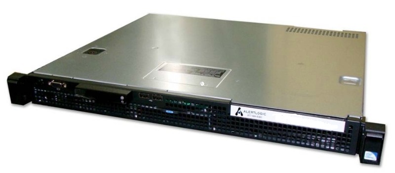
About the Alert Logic physical appliance
The Alert Logic appliance is a compact, Dell PowerEdge R220 1U rack server. Your appliance includes a chassis with front panel and back panel features, and rails for racking.
The information below is excerpted from the Dell PowerEdge R220 Technical Guide, available on the Dell Web site.
Chassis description
The PowerEdge R220 is a 1-socket 1U half depth server. The configuration details are as follows:
HDD Type
- 2 x 3.5 chipset-based SATA, PERC S110 (embedded SW RAID)
- 2 x 2.5 chipset-based SATA, PERC S110 (embedded SW RAID)
PSU Type: Single Non-Redundant, 250W
Diagnostic: LED
Processor: Intel Xeon processor E3-1200 v3 product family
DIMMs: 4 DDR3 1600MHz
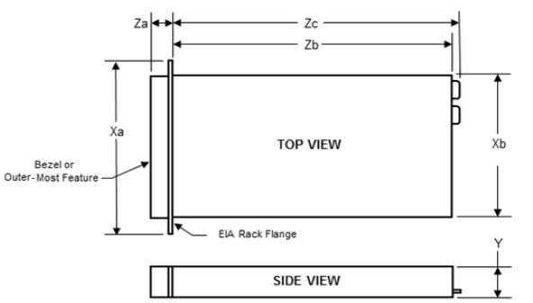
The following tables explain the Dell R220 dimensions.
Dimensions and weight
| Unit | Measurement |
|---|---|
| Dimensions w/o ear and bezel (H x W x D) | 1.67” x 17.09” x 15.4” (42.4 x 434 x 394.3 mm) |
| Max weight | 17.76 lbs (8.058 kg) |
Specific measurements
| Dimension | Measurement |
|---|---|
| Xa | 482 mm |
| Xb | 434 mm |
| Y | 42.4 mm |
| Za with bezel | 35 mm |
| Zb* | 390.7 mm |
| Zc | 394.3 mm |
| Max weight | 8.05 kg |
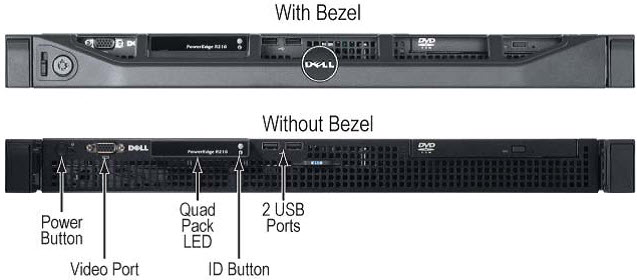
Front panel features and indicators
The following table explains the Dell R220 front panel features and indicators.
| Item | Indicator, button, or connector | Icon | Description |
|---|---|---|---|
| 1 | Power-on indicator/power button |

|
ACPI-compliant power button with an integrated green power LED. Note When powering on the system, the video monitor can take from several seconds to over 2 minutes to display an image, depending on the amount of memory installed in the system. Note On ACPI-compliant operating systems, turning off the system using the power button causes the system to perform a graceful shutdown before power to the system is turned off. |
| 2 | NMI button |

|
Recessed non-maskable interrupt (NMI) button used to troubleshoot software and device driver errors; use only if directed to do so by qualified support personnel or by the operating system's documentation. |
| 3 | Video connector |

|
Connects a monitor to the system. |
| 4 | Hard drive activity indicator | Lights up when the hard drive is in use. | |
| 5 | Diagnostic indicator lights | The four diagnostic indicator lights display error codes during system startup. | |
| 6 | System status indicator | Lights blue during normal system operation. Lights amber when the system needs attention due to a problem. | |
| 7 | System identification button |

|
The system identification buttons on the front and back panels can be used to locate a particular system within a rack. When one of the buttons is pushed, the system status indicators on the front and back panels light blue until one of the buttons is pushed again. |
| 8 | USB connectors (2) |

|
Connects USB devices to the system. The ports are USB 2.0-compliant.Up to five USB ports connect USB devices to the system |
| 9 | System identification panel | A slide-out panel for system information including the Express Service Tag, embedded NIC MAC address, and iDRAC6 Enterprise card MAC address. Space is provided for an additional label. | |
| 10 | Optical drive (optional) | One optional slim-line SATA DVD-ROM drive or DVD+/-RW drive, or combination CD-RW/DVD drive (when available).
Note Alert Logic appliances do not include optical drives |
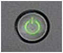
Power button LED
The power button controls the system's power, turning the unit on and off. All PowerEdge servers have the Power LED light-pipe integrated in the Power button. The color of the power LED is green. The lighting pattern must be in the form of a standard Power icon.
System status/ID LED
The system status/ID LED, present on non-modular rack-dense and rackable tower PowerEdge servers, has the following states:
- No light—System is in the off state (S5, or mechanical (no AC power))
- Blinking Amber—System fault/error condition
- Steady Blue—Normal operating state (S0)
- Blinking Blue—System ID engaged
This LED remains powered during non-operational (standby, shutdown) modes to enable system identification.
Back panel features and indicators
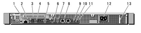
| Item | Indicator, button, or connector | Icon | Description |
|---|---|---|---|
| 1 | iDRAC7 Enterprise port (optional) |

|
Dedicated management port for the optional iDRAC7 Enterprise card. Note The Alert Logic appliance does not ship with an iDRAC7 Enterprise card. |
| 2 | VFlash media slot (optional) |

|
Supports one vFlash media card; functionality is activated only when iDRAC Enterprise is enabled. |
| 3 | PCIe expansion card slot | Connects a PCI Express expansion card. | |
| 4 | Serial connector |

|
Connects a serial device to the system. |
| 5 | Video connector |

|
Connects a VGA display to the system; One connector on front panel for rack mount. |
| 6 | eSATA |

|
Connects additional storage devices. |
| 7 | USB connectors (5) |

|
Connects USB devices to the system. The ports are USB 2.0-compliant. |
| 8 | Ethernet connectors (2) |

|
Embedded 10/100/1000 NIC connectors; choice of network connectors through the Select Network Adapter
family.
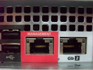
Note The left-most onboard NIC is the Alert Logic Management NIC and is indicated by a “MANAGEMENT” label. |
| 9 | System status indicator | Lights blue during normal system operation. Lights amber when the system needs attention due to a problem. | |
| 10 | System identification button |

|
The system identification buttons on the front and back panels can be used to locate a particular system within a rack. When one of the buttons is pushed, the system status indicators on the front and back panels light blue until one of the buttons is pushed again. |
| 11 | System identification connector | Connects the optional system status indicator assembly through the optional cable management arm. | |
| 12 | Power supply | 250 W power supply. | |
| 13 | Retention clip | Secures the power cable. |
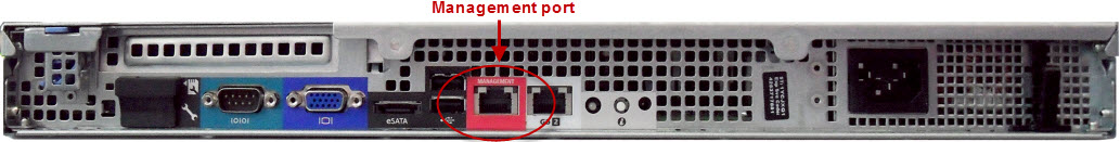
Management port
The Alert Logic appliance rear panel includes an Ethernet management port, framed in red.
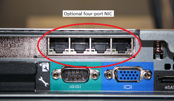
NIC for additional network ports (Threat Manager physical appliances only)
This optional NIC, available only for Threat Manager physical appliances, provides up to four additional network monitoring ports. During the onboarding process, Alert Logic requests the number of ports you require for your network. If you require additional network ports, Alert Logic orders and installs the appropriate NIC.
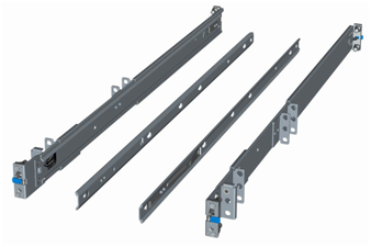
Rails
Your Alert Logic appliance ships with ReadyRails™ in the box. ReadyRails are static rails for toolless mounting in 4-post racks with square or unthreaded round holes or tooled mounting in four-post threaded and two-post racks.The R220 rails must first be attached to the sides of the system and then inserted into the cabinet members installed in the rack.
Power supply specifications
The Alert Logic appliance includes a single 250W power supply, which provides power to the planar, the internal hard drive bays, and one slim optical disk drive bay. Power is soft-switched, allowing power cycling using a switch on the front of the system enclosure or through software control (server management functions). The power system is compatible with industry standards, such as ACPI and Server 2000. The power supply is equipped with automatic input voltage detection.
| Feature | Non-redundant power supply |
|---|---|
| Dimensions | L-210 mm x W-106 mm x H-40 mm |
| Status Indicators | None |
| Integrated Fans | One |
| AC Cord Rating | 15 Amps @ 120 VAC, 10 Amps @ 240 VAC |
| Input Voltage | 100–240 VAC |
| Auto-ranging | Yes |
| Line Frequency | 50–60 Hertz |
| Maximum Inrush Current | Under typical line conditions and over the entire system ambient operating range, the inrush current may reach 55 Amps for 10 ms or less. |
| Hot-plug Capability | No |
| Output Power | 250W |
| Maximum Heat Dissipation | 1040 BTU per hour maximum |
| Efficiency
20% to 100% Load |
82% to 85% @ 115 VAC
82% to 85% @ 230 VAC |
Related topics