Set up an Alert Logic Threat Manager manual deployment on a physical appliance
This topic describes setup procedures for a manual deployment of Alert Logic Threat Manager on a physical appliance. This topic includes installation of the Alert Logic physical appliance and the steps required to complete your Threat Manager deployment.
Claim your Appliance
You must copy the Unique Registration Key to claim your appliance.
To access your Unique Registration Key:
- Click the Settings menu icon (
 ) in the upper right-hand corner.
 - Click Support Information.
- On the Details page, note your Unique Registration Key.
- Visit the URL that refers to the appliance to be claimed. This URL is https://<Appliance Public IP>. This URL will take you to a web page where you can enter the appliance's Unique Registration Key.
- Submit the Unique Registration Key on the appliance claim page accessed at the appliance URL you generated from its public IP address, and then click Claim Appliance.
Install the physical appliance
Before you install the Alert Logic physical appliance, see the Dell hardware documentation for Threat Manager appliances for information about how to connect the physical appliance to your network. Refer to the System Requirements page for the minimum system requirements to communicate with the physical appliance.
To install the physical appliance:
- Use the enclosed installation instructions to properly mount the appliance in the rack.
- Use the ports on the back panel to connect the appliance to your network.
- Connect a network cable from the red Ethernet management port on the appliance to the switch port and VLAN associated with the IP address allocated for the appliance.
-
Connect the network cable from the appliance monitor ports to the switch ports or network taps. The number and media type of monitor ports vary based on deployment.

With the exception of the red Ethernet management port, any Ethernet port may be used as a monitor port.
- Connect to a power source, and then press the power button.
- The appliance provides power auto-sense support for 100-240 VAC at 50/60 Hz.
- On older models, the power light does not display when you power on the appliance.
Ethernet activity lights can flicker, even when the appliance is off. - Contact the Alert Logic Security Operations Center (SOC) to request a connectivity test.
- In the US, call (877) 484-8383, and then select option 2.
- In the EU, call +44 (0) 203 011 5533, and then select option 2.
Change the internal IP address for a physical appliance
Alert Logic ships appliances with a preconfigured network IP address. If you need to add or update an appliance IP address, you must use the network configuration utility Alert Logic provides for this purpose.
To access the network configuration utility on the appliance, you must connect either of the following devices to the appliance:
- A USB keyboard and monitor connected to a USB connector and the VGA connector on the appliance.
- An IP-based KVM attached to the appliance.
To configure the network:
- Turn on the appliance.
- At the login prompt, use the login name setup and the password provided by Alert Logic.
- In the Configuration Utility, select Network Configuration, and then press Enter.
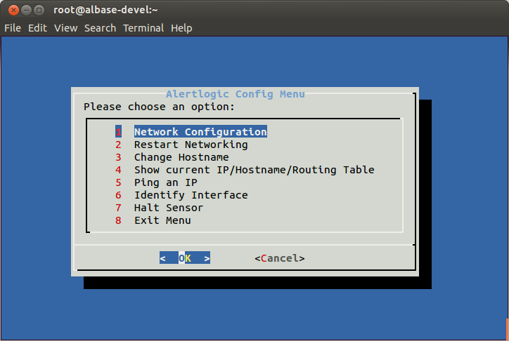
- Review the instructions, and then press Enter.
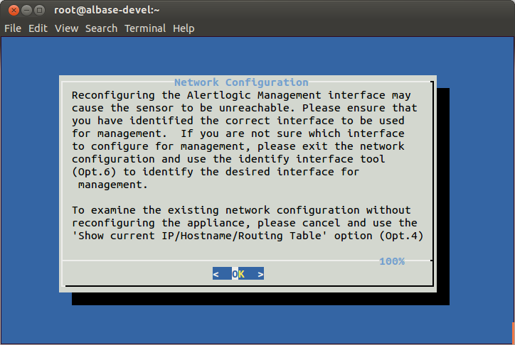
- Press Enter to continue.

- On the Interfaces screen, press Enter to continue.
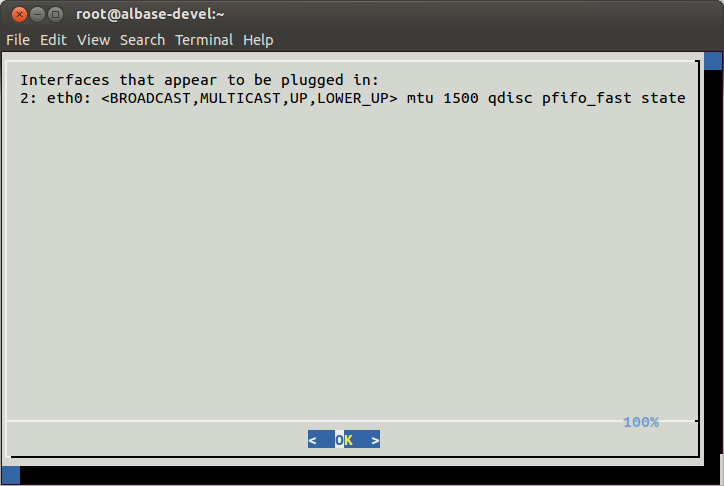
The Interfaces screen displays the connected interfaces. Typically, eth0 is the management interface as designated on the back of the sensor. However, other configurations could require management on a different interface.
- Select the desired management interface, and then press Enter.
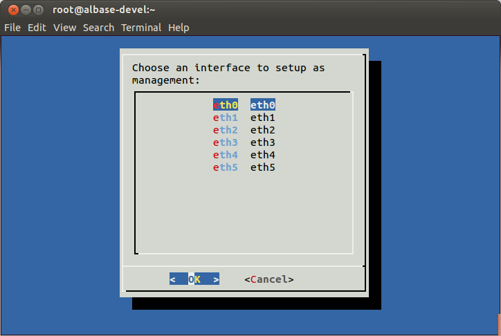
- Provide the IP address default gateway and subnet mask. Use the arrow keys to switch between fields.
Optional: Provide two DNS server IPs that the appliance can use instead of the default Google DNS servers.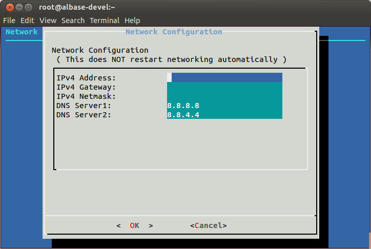
- Press Enter.
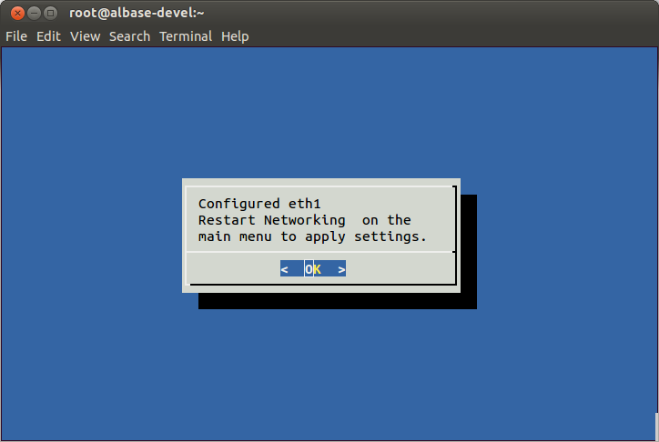
- Press Enter to confirm configuration.
-
Reconnect any network cables that you previously disconnected.
To apply network changes:
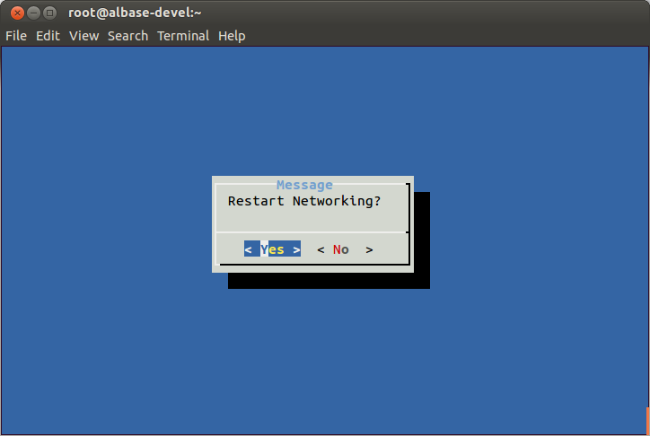
- From the Main Menu, select Restart Networking, and then press Enter to apply the configuration changes performed in the previous section.
- Select Show Current IP/Hostname/Routing Table to verify the changed interface and IP configuration.
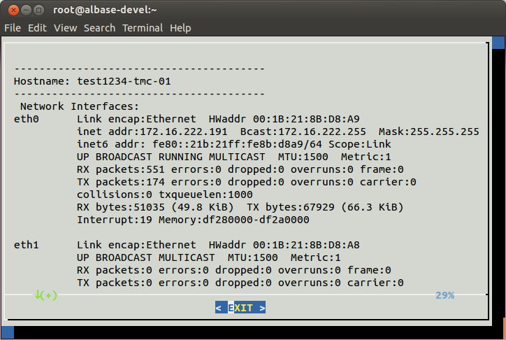
The configured Default Gateway appears with a destination of 0.0.0.0 , a flag of UG, and your enterprise default gateway. 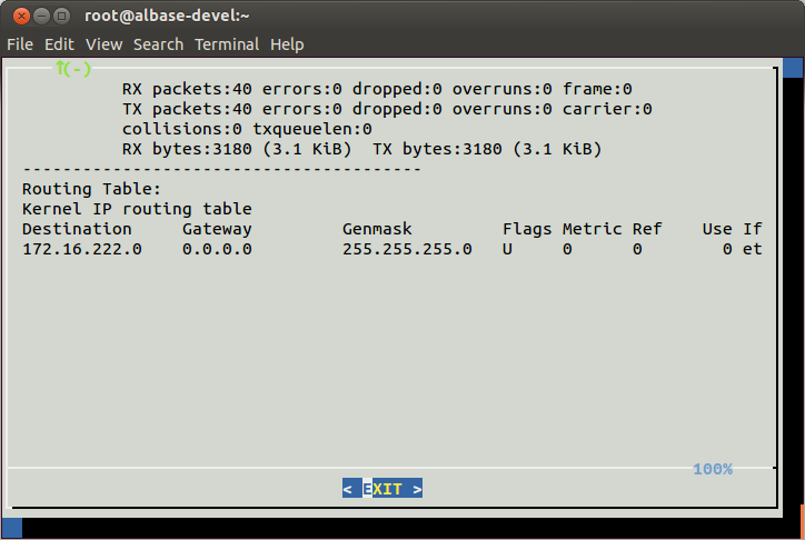
You can contact Alert Logic to verify connectivity with the appliance. The appliance should be reachable on your local network.
Confirm communication ability
You can perform this optional procedure to verify the physical appliance can communicate with other IP addresses.
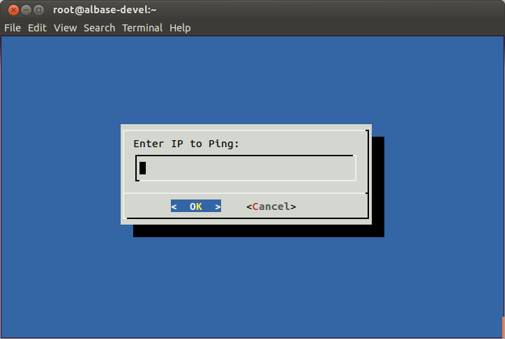
- From the main menu, select Ping an IP, and then press Enter.
- Provide an IP address in the form provided, and then press Enter.
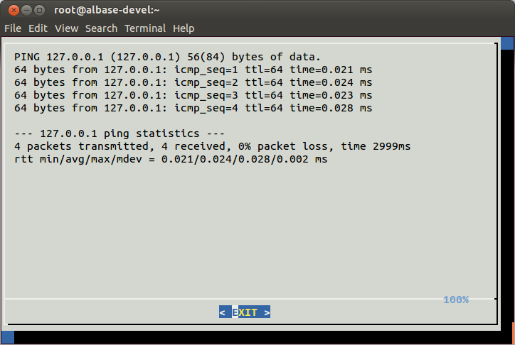
- After you verify communication with the IP address, press Enter.
Identify Interfaces
The Identify Interfaces tool flashes the Link LED of a selected detected interface to assist you with cabling and connections.
To identify interfaces:
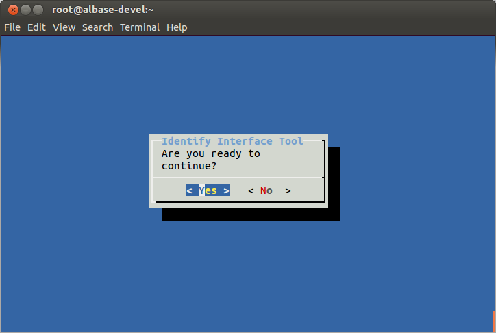
- From the Main Menu, select Identify Interface, review the instructions, and then press Enter.
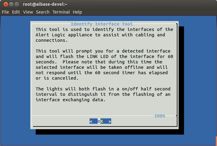
- To continue, press Enter.
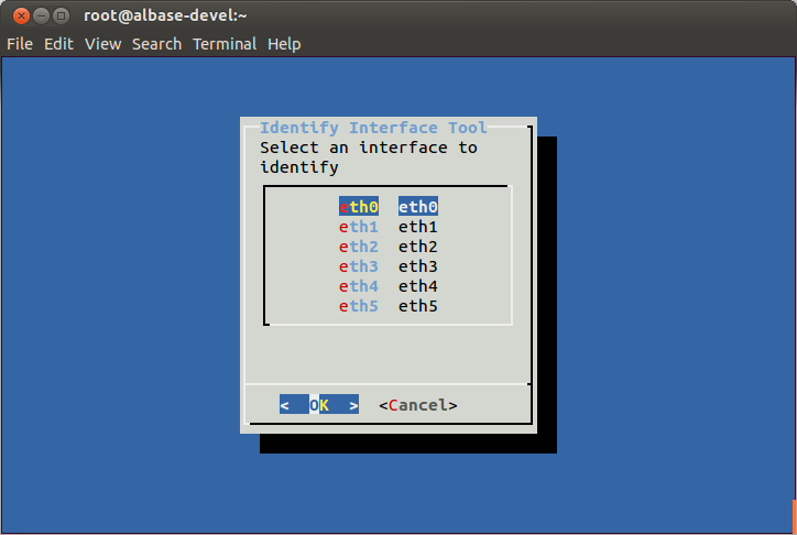
- Select the interface to identify, and then press Enter.
Test the network configuration
To test the network configuration:
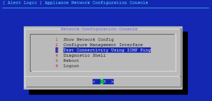
- From the Network Configuration Console, select Test Connectivity Using ICMP Ping.
- Enter the IP address of the default gateway.
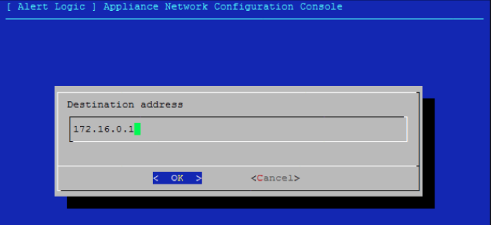
If you do not see a succession of ping responses, the connectivity test cannot ping the default gateway. Verify that the red Ethernet management port on the appliance is connected to the correct VLAN port, and that your IP information is correct.
-
After you ping the default gateway successfully, send an email to Alert Logic Onboarding. Provide the IP address of your appliance, or the NAT address if you use a separate internal and external addressing scheme.
Configure firewall rules
Before you complete set up of Threat Manager, you must adjust your firewall rules so data can be securely transferred to and from Alert Logic, and so product updates can occur. For information on firewall rules for the physical appliance, see:
- Threat Manager Physical Appliance Firewall Rules (US Data Center)
- Threat Manager Physical Appliance Firewall Rules (EU Data Center)
Deployment call
Alert Logic Deployment Services team works with you, by phone, to complete the setup process and prepare Threat Manager for use in your environment.
Claim the appliance
Your deployment call includes the appliance claim process, which links your physical appliance with your Cloud Defender account. You must claim your physical appliance before you can use Threat Manager.
Add home net settings
Your deployment call includes home net setup, which defines a set of IP addresses local to your Threat Manager appliance.
After setup, IP addresses that appear on your screen displayed in green are part of the home net. IP addresses displayed in black are not part of the home net. This color code helps you quickly recognize IP addresses and their respective states in your home net settings.
Set up network traffic monitoring
Threat Manager allows you to monitor network traffic through a SPAN session or network tap—the preferred method for network traffic ingestion for this deployment—or through the use of the Alert Logic agent.
The preferred method to monitor network traffic for a manual deployment on a physical appliance is to either create a SPAN session, which uses port mirroring to send a copy of the network traffic to the physical appliance, or install a network tap device that sits inline and mirrors traffic to the physical appliance. You must configure the SPAN session or network tap device before your scheduled call with Alert Logic Deployment. If you have specific questions with regard to configuration, contact Alert Logic Technical Support at (877) 484-8383 in the US, or +44 (0) 203 011 5533 in the UK.
If your environment includes devices that cannot be covered by a SPAN session or a network tap, you can download and install the Alert Logic agent to monitor network traffic. Your scheduled deployment call includes time allotted to deploy agents, if necessary.
Threat Manager uses agents to gather data from computers in your environment. You must download and install the Alert Logic agent, and then configure the collection sources to send data to the appliance for your systems to be monitored.
For agent download and installation information, see:
Create an assignment policy
An assignment policy is a set of rules that indicates the traffic that appliances should either accept or ignore. An assignment policy directs protected hosts to encrypt traffic and send traffic to specific appliances. In a dynamic environment where IP addresses often change, an assignment policy ensures that hosts always correspond to their appliances.
Threat Manager automatically creates a default assignment policy for each appliance. You can use the default assignment policy, or you can create a new assignment policy in Threat Manager.
To create an assignment policy:
- At the top of the Alert Logic console, from the drop-down menu, click Threat Manager, and then click Policies
- In the left navigation area, click Assignment.
- Click the Add icon (
 ).
). - In the Appliance Assignment Policy Name field, enter a name.
- In the Appliances field, select one or more appliances.
- Click Save.
Enable scans
Threat Manager allows you to run internal vulnerability scans from the Alert Logic appliance in your environment. This feature allows you to enable and disable internal scanning from the appliance interface. For more information about scans, see Scans.
To enable scans:
- At the top of the Alert Logic console, from the drop-down menu, click Threat Manager, and then click Deployments.
- On the Deployments page, click a deployment tile.
- In the left navigation area, click Appliances.
- In the list of appliances, click the pencil icon (
 ) for the appliance you want to modify.
 - In the right panel, click Enable Scans.
- Click Save.
Effects on performance
Scans can affect the performance of your appliance, depending on the number of cores in your environment. The following table illustrates the effect on performance.
| Number of cores | Performance impact |
|---|---|
| 4* | 50% |
| 8 | 17% |
| 16 | 7% |
| * Minimum required number of cores. | |